Rendered from electronics/ELECTRONICS.md in the repository at build time.
Estimates are labelled as such in the source; nothing on this page is a measured result unless it says so.
ValiTilt electronics#
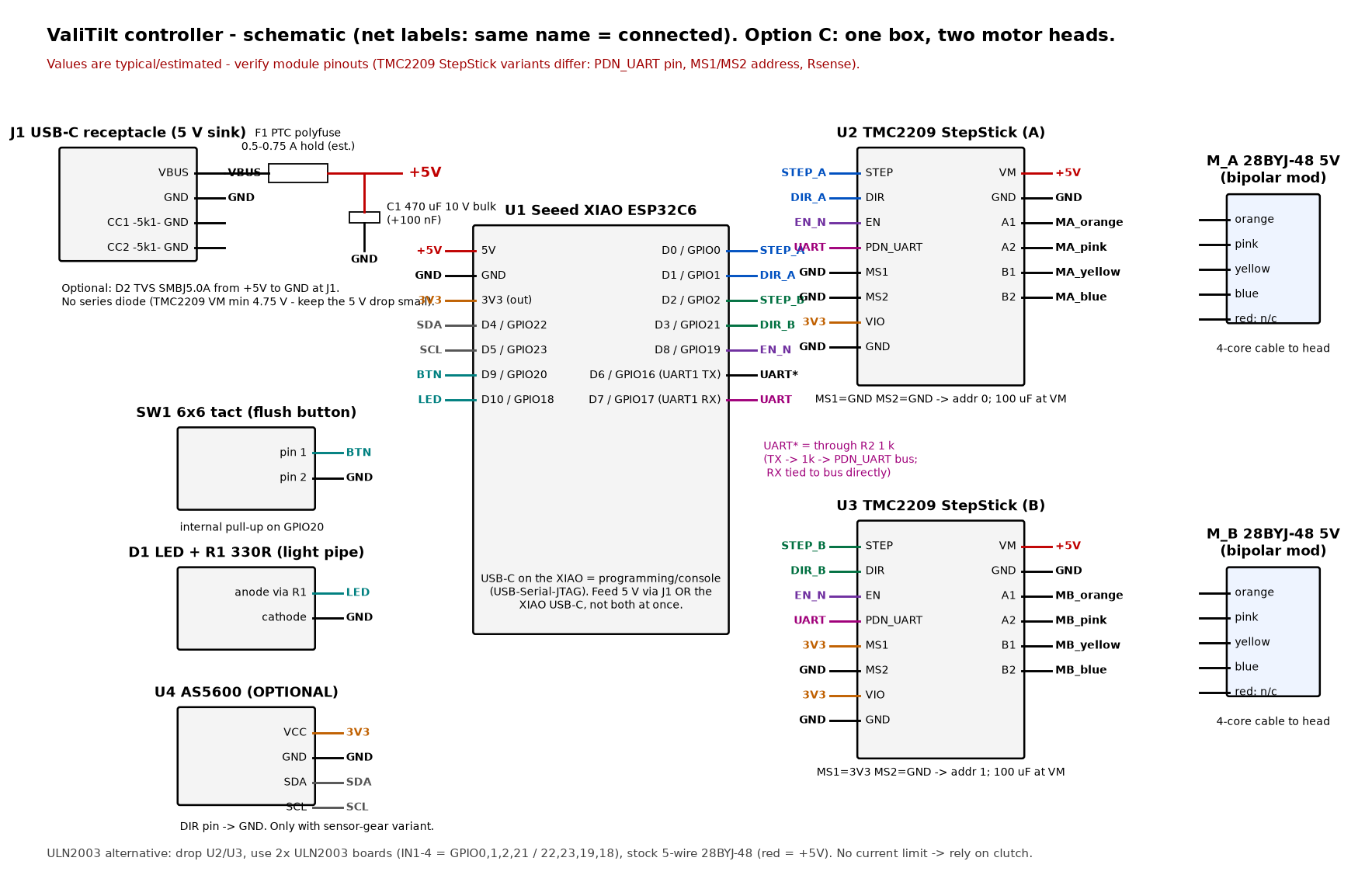
Rendered schematic: schematic.png (net-labelled, generated by tools/schematic.py).
All values are typical/estimated. Verify every module pinout - TMC2209 StepStick
clones differ (PDN_UART pin, MS1/MS2 addressing, Rsense value).
0. Cost-down default build (round 5, 2026-10-17): 2x ULN2003A, versions A / B / C#
This section is the default build from round 5 on. §1-§2 and §4-§5 describe the TMC2209 build, kept as the quiet option (StealthChop, current limit, bipolar-modded motors). §10 is the old LiFePO4/BQ25570 study. Values are typical or estimated unless a source is given. Verify every board pinout against your parts.
| Version | Power | Controller box (hardware/cad/ebox.scad) |
|---|---|---|
| A | 5 V USB-C wall supply, always plugged in | power_variant="usb" |
| B | 2000 mAh 1S LiPo, charged over USB-C | power_variant="battery" |
| C | as B + 12 V 1.5 W panel between the panes (pane_pack.scad) |
power_variant="solar" |
Common to all three: Seeed XIAO ESP32C6, 2x ULN2003A (DIP-16, one per motor) soldered on the perfboard, stock 5-wire 28BYJ-48 (no bipolar trace cut), one 5-pin JST-PH header per head, 6-wire flat cable to the head.
0.1 ULN2003A wiring (per motor, both versions)#
 XIAO GPIO --> ULN pin 1 IN1   OUT1 pin 16 --> motor pin 1  blue
 XIAO GPIO --> ULN pin 2 IN2   OUT2 pin 15 --> motor pin 2  pink
 XIAO GPIO --> ULN pin 3 IN3   OUT3 pin 14 --> motor pin 3  yellow
 XIAO GPIO --> ULN pin 4 IN4   OUT4 pin 13 --> motor pin 4  orange
               ULN pin 5-7 IN5..IN7 -> GND (unused channels; OUT5..OUT7 open)
               ULN pin 8  GND -> GND
               ULN pin 9  COM -> +5V_MOT (flyback clamp diodes)
                                          motor pin 5  red (common) -> +5V_MOT
 5-pin JST-PH header on the perfboard, pin 1..5 = blue, pink, yellow, orange, red.
- Coil order is the order of the common ULN2003 boards and of the firmware half-step table
(
firmware/main/uln2003.cpp: IN1..IN4 = blue, pink, yellow, orange). Verify: if a motor only buzzes, the order is wrong; if it turns the wrong way, set the direction in firmware. - The stock motor lead (5-pin JST-XH, about 240 mm) is cut and spliced to the 6-wire flat cable inside the head (5 of the 6 cores; the 6th is a spare). The box end gets a crimped 5-pin JST-PH housing.
- +5V_MOT bulk: one 470 uF / 16 V electrolytic next to the ULNs. Unused ULN inputs to GND.
- Current (ESTIMATE): 28BYJ-48 datasheet 50 ohm per half-coil; after the ~0.65-0.95 V Darlington drop about 86 mA per energised half-coil, about 130 mA average in half-step, about 0.64 W per moving motor from 5 V. The motor listing says 200 ohm DC resistance instead - measure one coil (red to any colour) with a meter; at 200 ohm current and power are about 4x lower and torque is lower too.
- There is no current limit: the O-ring clutch is the only torque limit. Coils are released between moves.
- Louder than the TMC2209 (full-current half-steps, no StealthChop). Run 3 rpm, homing 2 rpm (pull-in limit).
0.2 Version A (USB-C): pin map and power path#
| XIAO pin | GPIO | Function |
|---|---|---|
| D0 | GPIO0 | A_IN1 (motor A, ULN U2 pin 1) |
| D1 | GPIO1 | A_IN2 |
| D2 | GPIO2 | A_IN3 |
| D3 | GPIO21 | A_IN4 |
| D4 | GPIO22 | B_IN1 (motor B, ULN U3 pin 1) |
| D5 | GPIO23 | B_IN2 |
| D8 | GPIO19 | B_IN3 |
| D7 | GPIO17 | B_IN4 (moved off GPIO18, review M9) |
| D9 | GPIO20 | button to GND (internal pull-up) |
| D10 | GPIO18 | status LED: 330R -> 3 mm LED -> GND, behind the 0.6 mm lid skin |
| D6 | GPIO16 | free |
This is the map of the engineer's firmware fixes (VT_ULN_B_IN4 = GPIO17, LED stays on GPIO18).
 USB-C receptacle breakout (CC1, CC2: 5k1 to GND each) --VBUS--> F1 PTC 0.5 A hold --> +5V
 +5V --> XIAO 5V pin, ULN U2/U3 pin 9, both motor red wires, C1 470 uF
 Do not plug the XIAO's own USB-C while the box is powered (no diode-OR), or flash with the box unpowered.
0.3 Versions B and C (LiPo, Adafruit 6106 + MCP1700): pin map#
The B/C build needs two more GPIOs (VBAT sense on an ADC pin and the motor-power enable), so it uses all
eleven XIAO pins. This map needs a firmware change (today's firmware stops with #error for ULN + solar).
| XIAO pin | GPIO | Function |
|---|---|---|
| D0 | GPIO0 | A_IN1 |
| D1 | GPIO1 | A_IN2 |
| D3 | GPIO21 | A_IN3 |
| D6 | GPIO16 | A_IN4 (U0TXD: toggles during the boot log; harmless, +5V_MOT is off at boot) |
| D4 | GPIO22 | B_IN1 |
| D5 | GPIO23 | B_IN2 |
| D8 | GPIO19 | B_IN3 |
| D7 | GPIO17 | B_IN4 |
| D2 | GPIO2 | VBAT_SENSE (ADC): 1M from BAT+ / 1M to GND, 100 nF |
| D10 | GPIO18 | MOT_PWR_EN -> 6106 EN (boost on = motor rail on), 100k pull-down |
| D9 | GPIO20 | button to GND |
| (onboard) | GPIO15 | status LED = the XIAO's own user LED, seen through a light shroud and the 0.6 mm lid skin |
In sleep the firmware holds all eight coil GPIOs low (gpio_hold_en): an IN pin left high draws about
0.9 mA into the ULN's 2.7k input resistor even with the motor rail off.
0.4 Versions B and C: power path#
 USB-C (on the 6106) --VBUS--+
                             +-- 6106 on-board OR diodes --> bq25185 IN --> BAT (JST-PH on the 6106) --> 2000 mAh LiPo (PCM)
 C only: panel 12 V 1.5 W --VIN (6106 terminal block)--+                                          |
                                                        NTC 10k 3950 on the cell -> 6106 TS pad  |
 bq25185 VSYS (power path) --> MCP1700-3302E (TO-92, 1 uF in / 1 uF out) --> XIAO 3V3 pin (XIAO 5V and BAT pads unused)
 6106 TPS61023 boost (EN = MOT_PWR_EN) --> +5V_MOT 4.95 V --> ULN U2/U3 pin 9, motor red wires, C1 470 uF
- The TPS61023 has a true output disconnect in shutdown (TI datasheet, about 0.1 uA): with EN low the +5V_MOT rail is off, so no extra P-FET is needed to cut the ULN supply in sleep.
- The 6106 already ORs USB VBUS and the terminal-block VIN on the board, so an external Schottky between panel and USB is optional (not needed).
- Panel above about 7 V: the bq25185 is a linear charger, so the extra voltage becomes heat in the charger. At 166 mA (panel maximum) that is under about 1.5 W in full sun (ESTIMATE); cold Voc about 14 V, under the 18 V input limit (ESTIMATE).
- Boost start-up: the TPS61023 can fail to start into a load above about 200 mA (board guide). Firmware enables MOT_PWR_EN with all coils off, waits for the rail to settle (bench: about 5 ms, measure), then starts stepping. Check start-up with the 470 uF bulk capacitor on the bench.
- Charge current: 1 A by default (0.5 C for 2000 mAh). Cut the board's SJ1 jumper for 500 mA if preferred. The 6 h safety timer is fixed.
SAFETY REWORK on the Adafruit 6106 - no rework, no B/C build#
- 0 C charge cutoff (R16 -> NTC). On the 6106 the bq25185 TS/MR pin is tied to GND through a fixed 10k resistor (R16, 0402) and not broken out, so the charger never sees the cell temperature. Remove R16 and wire the cell's 10k 3950 NTC between the TS pad and GND. The bq25185 then stops charging below 0 C (LiPo charge window 0-45 C). Check with a meter: TS to GND reads the NTC (~10k at 25 C). Correction (2026-10-18, docs/power-solar.md §D3): computed from the TI thresholds, a 10k B3950 NTC alone gives a window of about +4.6 C to 54.6 C, not 0-45 C (safe on the cold side, high on the hot side).
- Boost EN pull-up -> pull-down (R2). EN has a 100k pull-up (R2) to VSYS, so the boost would be on whenever the XIAO pin floats and holding it off costs about 37-42 uA. Remove R2 and fit a 100k pull-down from EN to GND on the perfboard. EN is driven by MOT_PWR_EN.
- VSYS for the MCP1700. VSYS is not on the 6106 header. Use R2's freed VSYS pad (thin wire) to feed the MCP1700; that keeps the power path (the board runs from USB/panel when the cell is low). Fallback: the BAT pad (no power path). Confirm with a meter which R2 pad is VSYS before soldering. Board facts from Adafruit's published schematic and board files; the rework itself is not yet tested.
0.6 Version D: cell in the pane pack (2026-10-18, paper design, see docs/power-solar.md Part D)#
Same box electronics and pin map as B/C (§0.3), without the cell. The 6106 rework differs:
- R16 removed; on TS: the 6.8k NTC (TDK B57164K682J) on the pack cell (via the lead) in parallel with 39k + 2.2k in series at the TS pad -> charge window about -20 C .. +42 C (computed; bench-test it). The 10k NTC (B4) is not used in D.
- Cut SJ1 and replace R20 600R with 1.2k -> charge current about 250 mA (0.18C for the 1400 mAh LT cell, also when USB-C charges a cold pack).
- R2 removed + 100k EN pull-down, MCP1700 from VSYS, VBAT divider on GPIO2: as B/C.
- Lead to the pack (about 50 cm, flat, under the gasket): PV+ -> 6106 VIN terminal, BAT+ -> 6106 BAT, GND, NTC -> TS. With 6 cores, double BAT+ and GND.
0.5 Firmware build switches (summary)#
VT_DRIVER_ULN2003=1 (default for round 5), VT_RUN_RPM 3, VT_HOME_RPM 2. B/C also VT_POWER_SOLAR=1
with the §0.3 map. The TMC2209 build (VT_DRIVER_TMC2209=1) remains the quiet option.
Battery builds with VT_POWER_MODES=1 re-home every VT_REHOME_DAYS (7) and enter a low-battery mode below 20 % reachable charge (exit 30 %). USB-C keeps daily re-home. Weekly re-home assumes drift over a week stays small; that is not bench-tested.
1. Block diagram (quiet option: TMC2209; one controller, two motor heads)#
flowchart LR
  PSU["5 V USB-C wall supply<br/>(1 A+, hidden low / behind curtain)"] -->|USB-C| BOX
  subgraph BOX["Controller box (ebox.scad, ~61x37x25 mm)"]
    J1["J1 USB-C sink<br/>CC 5k1 x2"] --> F1["F1 PTC 0.5-0.75 A"] --> R5(("+5V"))
    R5 --> XIAO["XIAO ESP32C6<br/>Matter / Thread or Wi-Fi"]
    R5 --> TA["TMC2209 A"]
    R5 --> TB["TMC2209 B"]
    XIAO -- "STEP/DIR/EN + 1-wire UART" --> TA
    XIAO -- "STEP/DIR/EN + 1-wire UART" --> TB
    XIAO --- BTN["flush button"]
    XIAO --- LED["LED + light pipe"]
  end
  TA -->|"4-core flat cable ~1-1.5 m (est.)"| HA["Head A (right sash)<br/>28BYJ-48 + cup on knob"]
  TB -->|"4-core flat cable ~3-4 m (est.)<br/>along frame + head rail"| HB["Head B (left sash)"]
  XIAO -. "Thread 802.15.4 / Wi-Fi" .-> CTRL["Matter controller<br/>Google / Apple / HA / Aqara<br/>(+ Thread border router)"]
ASCII version:
 [5V USB-C PSU]==USB-C==>[ CONTROLLER BOX ]
                          J1 USB-C -> F1 PTC -> +5V --+--> XIAO ESP32C6 (5V pin)
                                                      +--> TMC2209 A (VM) ---4 wires---> HEAD A (28BYJ-48, bipolar)
                                                      +--> TMC2209 B (VM) ---4 wires---> HEAD B (28BYJ-48, bipolar)
                          XIAO D0/D1 -> STEP_A/DIR_A     XIAO D2/D3 -> STEP_B/DIR_B
                          XIAO D8 -> EN_N (both)         XIAO D6 -1k-+- D7 -> PDN_UART (both, addr 0 / 1)
                          XIAO D9 <- button (to GND)     XIAO D10 -> 330R -> LED (light pipe)
                          [optional] XIAO D4/D5 <-> AS5600 SDA/SCL (3V3)
2. Netlist (quiet option, TMC2209 backend)#
| Net | Connections |
|---|---|
| VBUS | J1.VBUS, F1.1 |
| +5V | F1.2, C1+ (470 uF), U1.5V, U2.VM, U3.VM, C2+ (100 uF at U2), C3+ (100 uF at U3), [D2 TVS cathode] |
| GND | J1.GND, J1.CC1 via R3 5k1, J1.CC2 via R4 5k1, C1-, C2-, C3-, U1.GND, U2.GND (both), U3.GND (both), SW1.2, D1.K, U2.MS1, U2.MS2, U3.MS2, [U4.GND, U4.DIR] |
| 3V3 | U1.3V3 (out), U2.VIO, U3.VIO, U3.MS1, [U4.VCC] |
| STEP_A | U1.D0 (GPIO0), U2.STEP |
| DIR_A | U1.D1 (GPIO1), U2.DIR |
| STEP_B | U1.D2 (GPIO2), U3.STEP |
| DIR_B | U1.D3 (GPIO21), U3.DIR |
| EN_N | U1.D8 (GPIO19), U2.EN, U3.EN (high = outputs off; add 10k pull-up to 3V3 so motors stay off during boot) |
| UART | U1.D7 (GPIO17, RX), R2.2, U2.PDN_UART, U3.PDN_UART |
| UART_TX | U1.D6 (GPIO16, TX), R2.1 (1 k) |
| BTN | U1.D9 (GPIO20), SW1.1 (internal pull-up) |
| LED | U1.D10 (GPIO18), R1 330R -> D1.A |
| SDA / SCL (opt.) | U1.D4 (GPIO22) / U1.D5 (GPIO23), U4.SDA / U4.SCL |
| MA_orange / MA_pink | U2.A1 / U2.A2 -> head A coil A (via 4-pin JST-PH) |
| MA_yellow / MA_blue | U2.B1 / U2.B2 -> head A coil B |
| MB_* | same for U3 -> head B |
3. Pin assignment - Seeed XIAO ESP32C6#
(Dx->GPIO per the Seeed wiki; verify for your board revision.)
| XIAO pin | GPIO | Function | Notes |
|---|---|---|---|
| D0 | GPIO0 | STEP_A | |
| D1 | GPIO1 | DIR_A | |
| D2 | GPIO2 | STEP_B | |
| D3 | GPIO21 | DIR_B | |
| D4 | GPIO22 | I2C SDA (AS5600, optional) | ULN2003 variant: B_IN1 |
| D5 | GPIO23 | I2C SCL (optional) | ULN2003 variant: B_IN2 |
| D6 | GPIO16 | UART1 TX -> 1 k -> PDN_UART | console moved to USB-Serial-JTAG |
| D7 | GPIO17 | UART1 RX <- PDN_UART | |
| D8 | GPIO19 | EN_N (both drivers) | ULN2003 variant: B_IN3 |
| D9 | GPIO20 | button to GND | |
| D10 | GPIO18 | status LED (light pipe) | ULN2003 variant: B_IN4 (then use onboard LED GPIO15) |
| 5V | - | +5V in (from J1 via F1) | do not also plug the XIAO USB-C at the same time unless you add a diode-OR |
| 3V3 | - | 3V3 out to VIO / AS5600 | |
| (onboard) | GPIO15 | user LED | strapping pin; ok as LED after boot |
| (onboard) | GPIO3/GPIO14 | RF switch (antenna select) | do not use; keep internal antenna default |
ESP32-C6-DevKitC-1 alternative: any free GPIOs work (avoid strapping pins 4, 5, 8, 9, 15 and USB D-/D+ 12/13); edit firmware/main/app_config.h.
4. TMC2209 notes (STEP/DIR/EN/UART, current limit)#
- UART mode: firmware sets
GCONF.pdn_disable=1,mstep_reg_select=1,I_scale_analog=0-> current comes fromIRUN/IHOLDregisters, the VREF potentiometer is ignored. Still turn the pot to a low setting (~0.1-0.2 V at the VREF test point, BTT-style formulaI_rms ~ VREF x 0.71 A/Vfor 0.11 Ohm modules - check your module's doc) so a wiring/UART failure can't cause a high current. - Addresses: on shared single-wire UART, U2 MS1=MS2=GND -> address 0; U3 MS1=VIO -> address 1.
- StealthChop:
en_SpreadCycle=0,TPWMTHRS=0= silent at all speeds;PWMCONFdefault (autoscale). - Current: 28BYJ-48 5 V coils are high-resistance (datasheets commonly list ~50 Ohm per
half-winding, measure yours). Bipolar-modded, a phase is ~2x that, so at 5 V the coil
itself limits current to roughly 50 mA.
IRUN(80 mA default) is therefore an upper bound;VT_IHOME_MA(35 mA) actually reduces torque for homing.vsense=1is used for fine current steps. - VM minimum 4.75 V (TMC2209 datasheet): keep the 5 V path short, no series diode; measure VM under load. If it sags, use a 5.2-5.4 V USB supply or the DRV8833/ULN2003 variants.
- Put 100 uF low-ESR at each VM pin (StepStick modules have little bulk capacitance).
- Never connect/disconnect a motor while VM is powered (can damage the driver).
5. 28BYJ-48: unipolar -> bipolar mod (for TMC2209 / DRV8833)#
- Pry off the blue plastic cover over the wire entry.
- On the small PCB, the red (common) wire's trace connects the two half-windings' centre taps. Cut that trace between the two coil pads with a sharp knife (usually the middle trace).
- Leave red unconnected. Coils are now orange+pink (coil A) and yellow+blue (coil B) - verify with a multimeter: each pair ~2x the old red-to-wire resistance; open between pairs.
- Refit the cover. Crimp a 4-pin JST-PH (or solder to the 4-core cable) in the order orange, pink, yellow, blue.
- If the motor runs backwards, swap the two wires of ONE coil (or set the direction in firmware).
6. ULN2003 alternative (cheapest)#
Stock 5-wire 28BYJ-48 + ULN2003 board per motor: red -> +5V, IN1..IN4 = GPIO0/1/2/21 (motor A)
and GPIO22/23/19/18 (motor B), set VT_DRIVER_ULN2003 1. 5 wires per head. Louder (full/half-step
current switching), no current limit (torque safety then relies on the clutch only) and
higher coil current (estimated 100-200 mA per motor while moving). Coils are switched off between moves.
7. Power budget (ESTIMATES - measure with a USB power meter; ULN default: §0.1 and docs/power-solar.md §C)#
| State | Option C (2 heads, TMC2209, Thread FTD) | Notes |
|---|---|---|
| idle (radio on, drivers off) | ~25-60 mA @ 5 V | ESP32-C6 802.15.4/Wi-Fi RX dominates (est.) |
| one motor moving | + ~50-120 mA | bipolar 28BYJ-48, coil-limited at 5 V (est.) |
| ULN2003 variant moving | + ~100-250 mA | unipolar, 2 phases on in half-step (est.) |
| Wi-Fi TX peaks | short peaks up to ~300 mA | Wi-Fi variant only (est.) |
| design rule | one motor at a time, total < ~300 mA | firmware queue enforces it |
A 5 V / 1 A USB charger leaves plenty of margin.
8. Battery variant notes (Option B, per head, UNVERIFIED)#
- XIAO ESP32C6 has battery pads and an on-board Li-ion charger (per Seeed) -> 1x 18650 (or a flat LiPo) + charging through the XIAO's USB-C.
- The 28BYJ-48 5 V needs ~5 V: add a boost converter with an EN pin (switched off between moves - cheap MT3608-type modules draw mA when idle) or run a 3.7 V-tolerant driver (DRV8833 2.7-10.8 V) and accept less torque.
- Firmware:
sdkconfig.defaults.battery(Thread MTD / ICD sleepy end device),VT_NUM_BLINDS 1. - Power estimate: sleep avg 0.1-0.5 mA (est.), 4 moves/day of
20 s at ~0.5 W -> roughly 0.02-0.06 Wh/day -> an 18650 (10 Wh nominal, ~70 % usable) lasts on the order of 4-12 months - wide range, unverified. 2xAA needs a boost to 5 V and sags under motor current; expect less. - Battery voltage sense: divider (2x 200k + 100 nF) to an ADC pin (GPIO0-6 are ADC on the C6).
9. Option A (each head its own controller, daisy-chained 5 V)#
Two complete heads (XIAO + 1 TMC2209 each inside a bigger head), 5 V daisy-chained with a 2-wire
jumper (JST-PH 2-pin) across the mullion/head rail. Two Matter nodes. Larger heads (electronics
in the cap, housing_slim.scad has_ui=true + extra height), more cost. Use it only if a cable
from one central box to both heads is impractical.
10. Solar + LiFePO4 variant (old study, superseded by §0.3-§0.4) - netlist (ESTIMATED values)#
Design rationale, budget and PVGIS harvest: ../docs/power-solar.md.
Power sheet: schematic_solar.png (tools/schematic_solar.py). Motor heads, UART,
button and TMC2209 wiring stay as in §2, except the pin changes and the gated motor rail below.
It replaces the 5 V USB supply as the running power. USB-C now only charges the cell.
| Net | Connections |
|---|---|
| PV+ | PV1.+ (panel, 4-5 series cells, Voc ≤ ~3.3 V cold), U5.VIN_DC, CIN 4.7 uF |
| VSTOR | U5.VSTOR, CSTOR 4.7 uF, U5.VOC_SAMP (→ MPPT 80 % Voc), top of the OV/OK dividers via U5.VRDIV |
| BAT+ | U5.VBAT, U6.BAT (CN3058E), BT1.+ via 1S LFP protection PCB + F2 (0.5 A), U7.VIN, U8.VIN, R10 (1M) top, CBAT 100 uF |
| VBUS | J1.VBUS via F1 PTC, U6.VIN (+ 10 uF) |
| VBAT_OK | U5.VBAT_OK → U7.ON (system load switch). Thresholds: OK_PROG 3.00 V falling, OK_HYST 3.20 V rising (resistors per BQ25570 datasheet, total ≤ ~13 MΩ) |
| 3V3_SYS | U7.VOUT, C 47-100 uF, U1.3V3 pin (XIAO 5V and BAT pads not connected), U9.VIN, U10.VDD (VEML7700) |
| MOT_PWR_EN | U1.D10 (GPIO18), R11 100k to GND, U8.EN (TPS61023), U9.ON |
| +5V_MOT | U8.VOUT (FB divider → 5.2 V, 22 uF), U2.VM, U3.VM (100 uF each, as before) |
| VIO_MOT | U9.VOUT, U2.VIO, U3.VIO, U3.MS1 (addr 1), R3 10k EN_N pull-up (was 3V3) |
| VBAT_SENSE | R10 (1M from BAT+) / R12 (1M to GND) mid-point, C 100 nF, U1.D2 (GPIO2, ADC1 ch2) |
| STEP_A / STEP_B | U1.D0 / U1.D3 (GPIO21) |
| DIR | U1.D1 → U2.DIR and U3.DIR (shared; one motor at a time) |
| SDA / SCL | U1.D4 / D5 → U10 VEML7700 (+ AS5600 if fitted), 4.7k pull-ups to 3V3_SYS |
| LED | on-board user LED GPIO15 (D10 is now MOT_PWR_EN) |
| U5 settings | VBAT_OV 3.50 V; VOUT_EN = GND (buck unused); EN = GND (enabled); LBOOST 22 uH; VREF_SAMP 10 nF |
| U6 settings | CN3058E ISET for ≈ 500 mA (formula in its datasheet); TEMP → NTC on the cell or per datasheet |
Rules:
- Never put a LiFePO4 cell on the XIAO battery pads (Li-ion 4.2 V charger).
- The BQ25570 rule "VBAT_OV must be higher than VIN_DC" → use a low-voltage panel. For a standard "5 V" panel use the SPV1050 instead (docs/power-solar.md §5). Keep the panel input ≤ 400 mW (recommended max).
- Heavy loads (radio TX peaks, the boost converter) come from BAT+, not from VSTOR.
- While MOT_PWR_EN is low, firmware holds STEP/DIR/EN_N low and the UART TX hi-Z (no back-powering of VIO). TMC2209 registers are re-written after every rail power-up.
- Solar variant battery/sleep budget: §3 of docs/power-solar.md (replaces the rough §8 estimate above for this variant).
Figures
electronics/schematic.png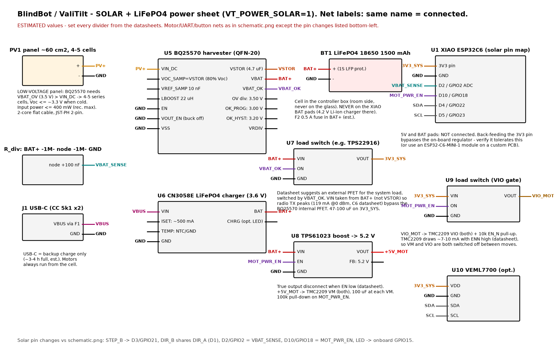
electronics/schematic_solar.png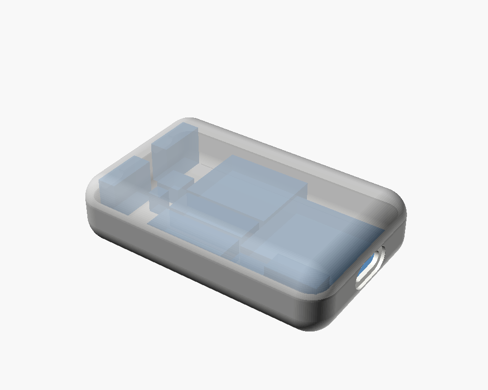
hardware/renders/ebox_A_inside.png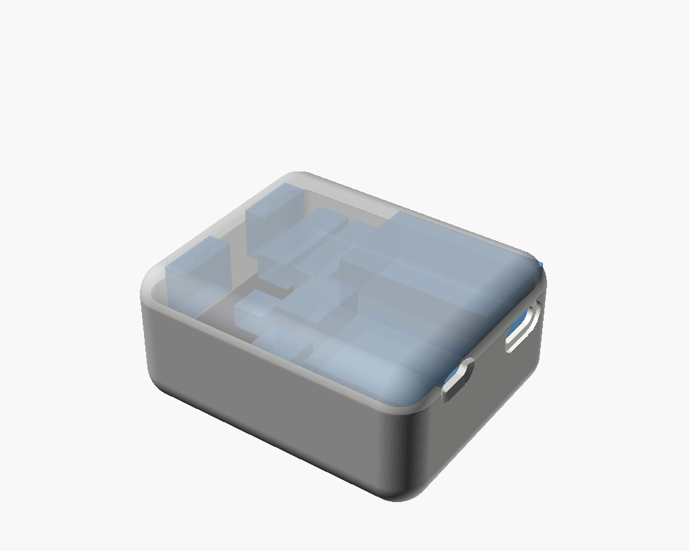
hardware/renders/ebox_C_inside.png